Since I had to go to work, I made the best out of the trip by documenting it.

Since I had to go to work, I made the best out of the trip by documenting it.
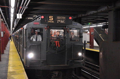
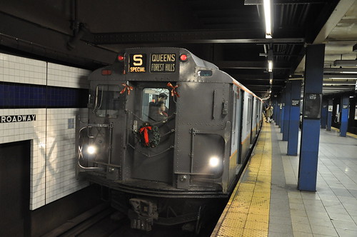
I finally managed to get pictures of the MTA Holiday Train.
→ No CommentsTags: MTA·Subway·Train
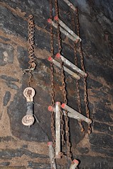
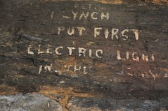
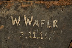
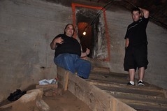
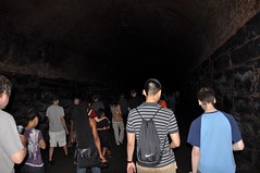
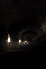
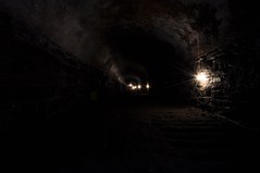
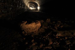
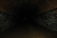
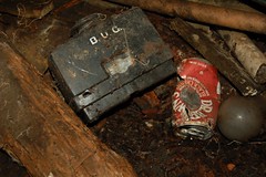
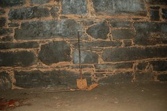
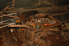
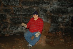
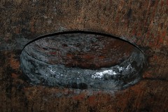
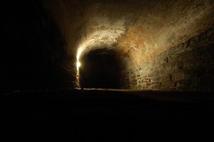
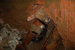
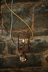
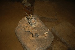
These pictures are from my second visit to the Atlantic Avenue Tunnel on June 20, 2010. Now since access to the tunnel has been banned, I want others to see what NYC has ruined for everyone.

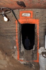
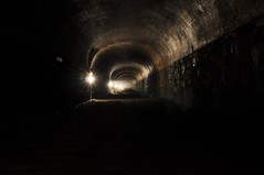


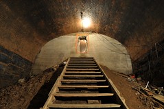
Here are the pictures from my first visit on April 20, 2008.


I decided to make my own GPS for my Nikon D90. Nikon wants well over $200 for a GPS unit. The parts I used cost roughly $40 in total, much less expensive than Nikon’s solution. The D90 accessory plug outputs +5V and expects 5V TTL logic. I was able to output +3.3V logic from my Arduino and it worked, but the GPS unit’s threshold must have been lower and the D90 didn’t accept the data. Below are the details on how I completed the task. I have left out the tracing and testing (e.g. checking to make sure I didn’t connect two pins or ground anything out) phases of the project in this writeup, but needless to say you should test and check your modifications with a multimeter.
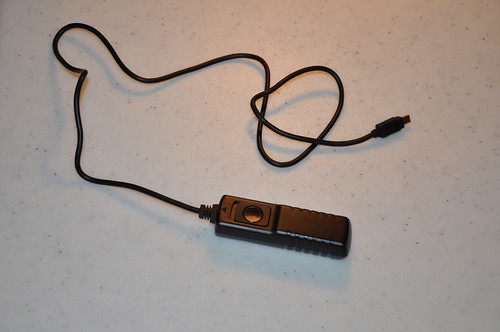
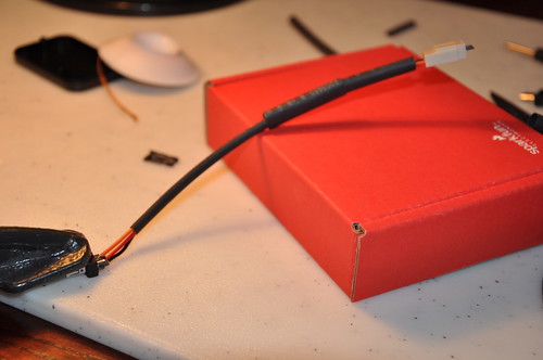
I started with a cheap knockoff remote shutter release cable from Ebay; cost $5-$6.
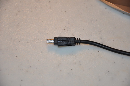
The connector needs to be cut apart since the the wire only has the pins soldered for the remote release (3 wires).
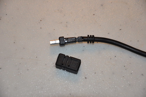
The outer molding removed.
After careful cutting the connector has been completely exposed.
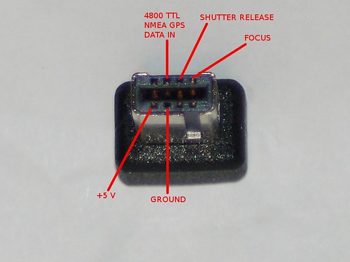
Here is the pinout of the connector for the D90.
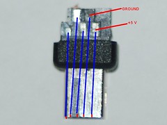
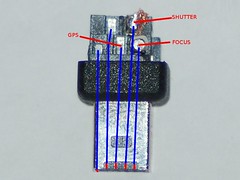
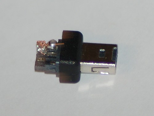
The corresponding solder pads, I’m not sure if all the connectors will have the same location of pads.
Soldering the molex connector wire onto the D90 plug. I decided to use this approach instead of hard wiring into the GPS for three reasons. I wanted to be able to disconnect from the GPS unit, still be able to use the USB output from the GPS and if the connector broke I could make a new jumper wire easier.
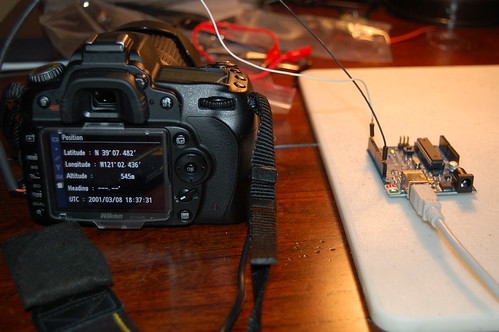
I wanted to test the connector after I finished soldering it, so I setup my Arduino to output some emulated NMEA GPS sentences. The D90 accepted the Arduino’s 3.3V logic.
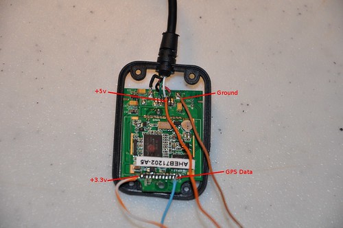
After tracing the pins from the PL2303 Serial to USB converter I was able to find larger pads to solder the +3.3V and GPS Data. The +5V is used for powering the GPS and as a reference voltage for the logic level converter. The 3.3V is used as reference for the logic level converter. This GPS unit cost $30 shipped off Ebay.
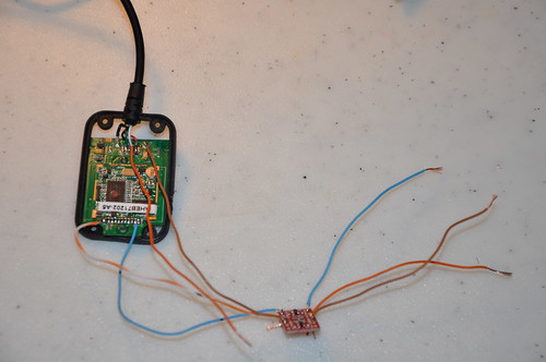
Here is the Sparkfun logic level converter hooked up to the GPS. The converter needs +5V and +3.3V as reference voltages to do the conversions.
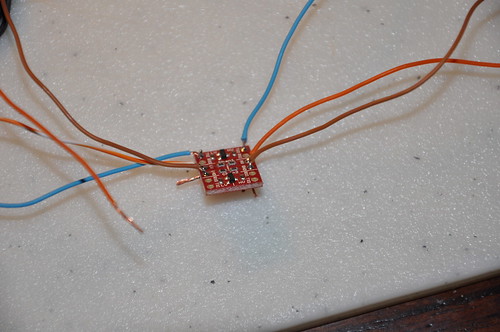
Closeup of the logic level converter. Cost under $2.
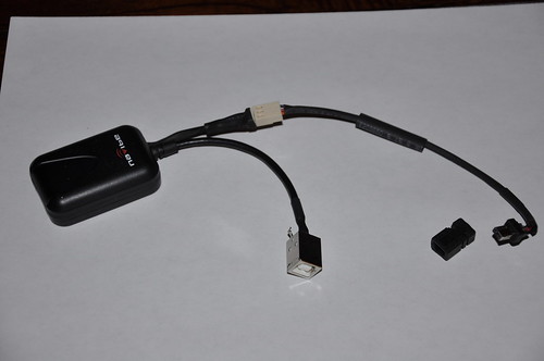
Here is the completed GPS. I didn’t take any pictures of soldering the USB connector. Since this picture I have epoxied the cover back into the connector to add strength and to prevent short circuiting. I would not connect the GPS to the computer and camera at the same time. If you do you will just want to connect the ground and GPS data lines and NOT THE +5V. You really don’t want the a voltage differential to go into your camera or vice versa.
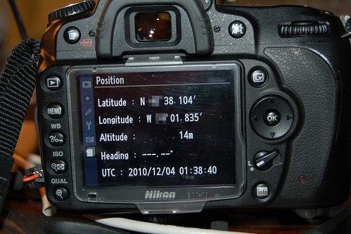
And we have real GPS data!
All things considered the project was definitely worth it and made me exercise some of my EE skills from college. I still need to figure out how I am going to mount the GPS to the D90. So now I will be able to geotag my photos when I am out taking pictures and won’t ever forget where I took one again.