
I decided to make my own GPS for my Nikon D90. Nikon wants well over $200 for a GPS unit. The parts I used cost roughly $40 in total, much less expensive than Nikon’s solution. The D90 accessory plug outputs +5V and expects 5V TTL logic. I was able to output +3.3V logic from my Arduino and it worked, but the GPS unit’s threshold must have been lower and the D90 didn’t accept the data. Below are the details on how I completed the task. I have left out the tracing and testing (e.g. checking to make sure I didn’t connect two pins or ground anything out) phases of the project in this writeup, but needless to say you should test and check your modifications with a multimeter.
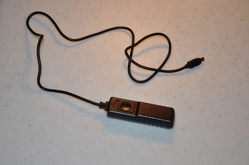
I started with a cheap knockoff remote shutter release cable from Ebay; cost $5-$6.
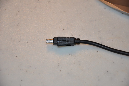
The connector needs to be cut apart since the the wire only has the pins soldered for the remote release (3 wires).
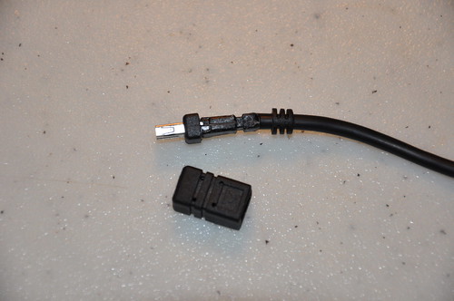
The outer molding removed.
After careful cutting the connector has been completely exposed.
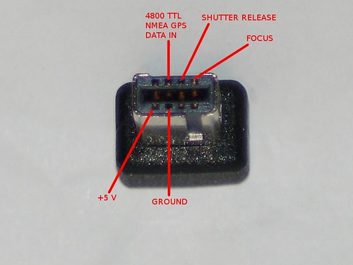
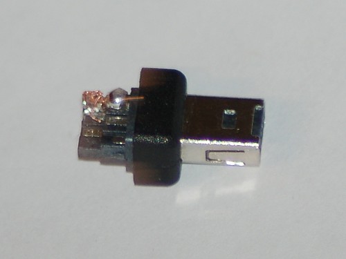
Here is the pinout of the connector for the D90.
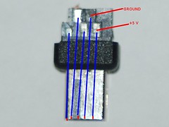
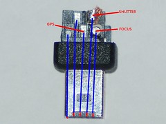
The corresponding solder pads, I’m not sure if all the connectors will have the same location of pads.
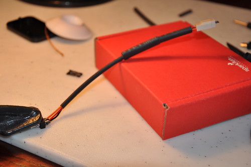
Soldering the molex connector wire onto the D90 plug. I decided to use this approach instead of hard wiring into the GPS for three reasons. I wanted to be able to disconnect from the GPS unit, still be able to use the USB output from the GPS and if the connector broke I could make a new jumper wire easier.
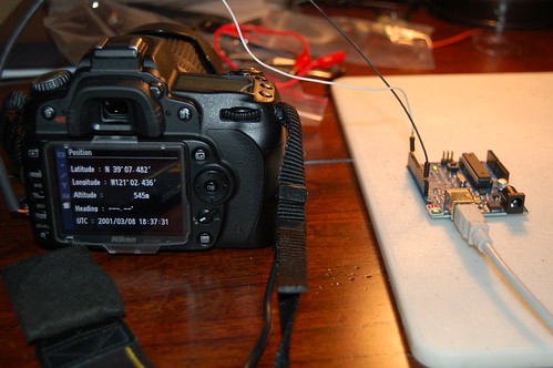
I wanted to test the connector after I finished soldering it, so I setup my Arduino to output some emulated NMEA GPS sentences. The D90 accepted the Arduino’s 3.3V logic.
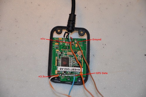
After tracing the pins from the PL2303 Serial to USB converter I was able to find larger pads to solder the +3.3V and GPS Data. The +5V is used for powering the GPS and as a reference voltage for the logic level converter. The 3.3V is used as reference for the logic level converter. This GPS unit cost $30 shipped off Ebay.
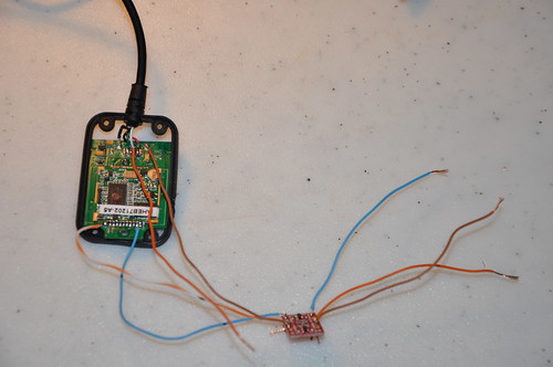
Here is the Sparkfun logic level converter hooked up to the GPS. The converter needs +5V and +3.3V as reference voltages to do the conversions.
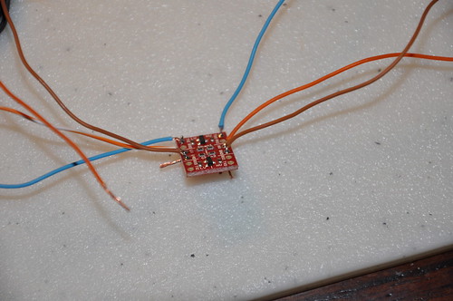
Closeup of the logic level converter. Cost under $2.
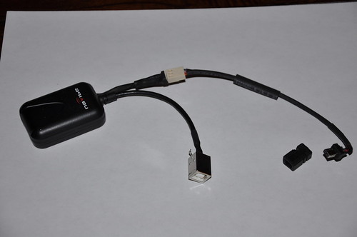
Here is the completed GPS. I didn’t take any pictures of soldering the USB connector. Since this picture I have epoxied the cover back into the connector to add strength and to prevent short circuiting. I would not connect the GPS to the computer and camera at the same time. If you do you will just want to connect the ground and GPS data lines and NOT THE +5V. You really don’t want the a voltage differential to go into your camera or vice versa.
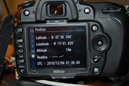
And we have real GPS data!
All things considered the project was definitely worth it and made me exercise some of my EE skills from college. I still need to figure out how I am going to mount the GPS to the D90. So now I will be able to geotag my photos when I am out taking pictures and won’t ever forget where I took one again.
George // Dec 6, 2010 at 17:59
Ahh, reminds me of good old senior design project days. Very nice write-up. Wish my Olympus eVolt was enable to encode GPS data into photos.
Max // Dec 6, 2010 at 19:29
Brilliant! I had thought about doing something similar but hadn’t find a cheap way around the proprietary connector. I didn’t realize that they were using that slot for remote triggers. I wonder if you could track down a manufacturer that would pin-out all the connections to a cable?
I’ve been thinking about doing some interesting things w/ the USB port, and would love to vampire-off the 5V of the GPS port. Any idea how much current you can sap off it?
-m
dan // Dec 6, 2010 at 19:55
Max,
I haven’t found anything short of the cable Nikon sells that you could cut in half.
I just took an amp reading and the GPS draws roughly 50mA. I don’t know how much you can pull on that pin. The +5V is always on, even when the camera is off. I think there is another pin that can output the +5V with the “auto meter” option in the GPS menu but then the GPS would have to re-acquire the GPS fix.
Fernando Lamarca (FLA) // Dec 16, 2010 at 09:17
Great job …
Thanks for putting the text clearer picture of the original.
Forgot password Flickr and I can not access my web.
See the link to Nikon with the progress of my work
Greetings
Fernando_FLA
http://www.nikonistas.com/digital/foro/index.php?showtopic=38837
Robert // Feb 15, 2011 at 17:40
This is awesome. Gonna have to give this a go if my Garmin Edge 705 doesn’t work.
Great write up!
Rafal // Feb 21, 2011 at 08:51
Hi!
On my D90 on pin as you describe +5V I have 6,5V. Is this pin connected directly to battery?
Is in D90 another pin with exactly +5V?
I am going to connect this GPS to camera.
http://www.propox.com/download/docs/GPS_FGPMMOPA6.pdf
Do you have idea how to connect it to D90? How make DC stabilizer and converter for different voltage level between GPS and camera?
Could you help me and give some advices.
Best regards,
dan // Feb 22, 2011 at 09:49
The +5V pin is +5V on my camera, the pin is powered even when the camera is turned off. You can buy a 3.3V regulator off the shelf and drop the voltage. I used a Sparkfun level converter (http://www.sparkfun.com/products/8745).
Rafal // Feb 22, 2011 at 11:21
Thanks for link to Sparkfun.
Maybe my multimeter is damaged and show wrong voltage on pin. I will check it.
BR.
DOUCET // Feb 22, 2011 at 09:33
Great job !
I would like to do the same, but I don’t understand why do you not use directly the +5V of the camera to power the GPS ? Why using a converter in 3,3v ?
Thanks
dan // Feb 22, 2011 at 09:44
I am using the 5V to power the GPS. The GPS chip outputs 3.3V TTL and the D90 expects 5V TTL, so that is why I used the logic level converter.
DOUCET // Feb 22, 2011 at 12:15
Okay, but I still don’t understand the use of the 3,3V output’s
Maybe it’s the connections that I’m not sure..
It’s not enough to connect the 5V power and the ground to the GPS and the GPS data to the camera ?
dan // Feb 22, 2011 at 12:18
The GPS I used was a USB GPS and I had to find the data out from the actual GPS chip which is 3.3V. The output from the GPS chip is connected to a PL2023 serial to usb converter that is at 5V, but you can’t use USB signals for the D90.
DOUCET // Mar 11, 2011 at 15:11
Okay, so if I well understand, you need to convert the GPS data in a 5V signal in order to be accepted by the camera ?
dan // Mar 15, 2011 at 07:22
Correct, the D90 expects 5V logic, even though most 5V logic devices can accept 3.3V logic, but the D90’s thresholds must be higher.
LouiZo // Apr 3, 2011 at 11:31
Thanks for your article that describe the pinouts! I’ve just done a test with a Pharos GPS-500 and the same connector you have (with a shutter cord). The power on my side is 6v and Pharos output is 3.3V, but plug directly, it works fine! no need to have a level shifter, at least on my D3100 😉
Thanks again !
LouiZo
Wells // May 13, 2011 at 08:49
Hi,
I got a GPS module, it output 4800 baud serial signal, and I found it has a ST232B ic to transform TTL signal to RS232 signal, so I line out the ttl signal from PIN12 of ST232B, the TTL signal is 5V, but D90 could not find the GPS device.
I connected Vcc to GPS module +5v
GND to GPS module GND
GPS Data to GPS module ST232B pin 11 (TTL output).
what’s wrong with my device?
my arduino can use TinyGPS library to got GPS data from my GPS module.
Can you provide the arduino test sketch for refference.
Thanks.
BR,
Wells.
Wells // May 13, 2011 at 09:07
Sorry,
Thanks,
I found my problem~
I connected the gps data pin to the ST232B pin 12.
I confirmed with the ST232B datasheet, found that it’s the ttl input pin. so it’s my mistake, now my GPS module works!
Thanks!
Dave // Jul 2, 2011 at 11:21
Here’s a suppier for the connector on a basic lead.
http://www.gadgetinfinity.com/product.php?productid=17586.
dan // Jul 2, 2011 at 11:38
Dave,
That looks like it just has pinouts for the shutter and focus, you need other pins for the GPS to work.
Bernd // Jul 3, 2011 at 15:50
Hi nice job!
Anyone having some info on how to make a bluetooth module for the nikon D90 to connect to various external gps loggers , like the I-blue , qstarz and so on.
Thank You
Luc // Aug 6, 2011 at 09:45
Hi, nice job, very usefull !
Tested on a Nikon D5100 , just work fine !
If this can Help for D5100 users :
– Vcc is 6V an permanent
– Gps data in is internally pulled up to 3V, so you can use a simple NPN transistor to translate signal from RS232.
( for example a 2N2222 with a 10K resistor on base, emitter to gnd an collector directly tied to Gps input : tested OK with a Garmin GPS )
Rahul // Sep 17, 2015 at 04:33
Hey there, thanks for the tip.. My camera doest recognise anything. is it because of level shift? can you elaborate on circuit for level shifter using 2n2222?? thanks
DIY Nikon D5100 GPS | Cyrozap's Tech Projects // Aug 13, 2011 at 20:44
[…] the GPS from here and the pinout data for the camera connector (with a lot of other useful info) here. Note: on the Flickr photo, read my comment for clarifying info and […]
zequ // Sep 9, 2011 at 22:36
hello i need one gps for my nikon D80 you can help me??
Josh // Sep 19, 2011 at 11:43
Hi Dan,
I’ve re-wired up a shutter-release cable, and I’d just like to emulate some GPS positions for my research. Can you give me an idea of the NMEA sentences you used?
I’ve been using Serial.begin(4800); and Serial.println(); with some of the examples at http://home.mira.net/~gnb/gps/nmea.html#gpgga but while the camera seems to detect the GPS messages – it allows me to go into “position”, which it didn’t before I debugged my code – it is set to “—, —” for everything.
Kind Regards,
Josh
dan // Sep 19, 2011 at 11:49
The minimum sentences you need is GPRMC and GPGGA. I used output from here: http://www.gpsinformation.org/dale/nmea.htm. There is a checksum at the end of the string, so an invalid checksum will void the data.
Hope this helps.
Jeffrey // Dec 5, 2011 at 11:19
This is excellent!
I wonder, would it be possible to log the position of the camera in space and write that into the exif data?
http://www.x-io.co.uk/node/9
that would be great. Do you know if it would be possible, or will only GPS info work?
dan // Dec 6, 2011 at 11:51
The camera only accept NMEA sentences. If you formulated the proper GPRMC and GPGGA sentences it would accept them.
Jacob // Dec 12, 2011 at 05:30
I have been looking for something like this on and off for nearly two years, I sold my D90 some time ago, and I am now going to get a D7000. I am a tinkerer of sorts, and I do enjoy building things myself, however, with regards to GPS and the construction done here, it seems I am a bit in the dark.
I am wondering if you could possibly give me a bit more detail than what you have on your site. i.e. I am a bit confused about the USB to serial adapter, what is the purpose, from what I can see, the navibe GPS unit uses USB, and should not require any sort of adapter. So a bit more detail would be greatly appreciated… If you would like, I have submitted my email and would thoroughly enjoy learning a bit more from you if you have the time.
~Jacob
dan // Dec 12, 2011 at 07:08
The cameras accept TTL level logic from the GPS. You can’t hook up a USB GPS directly to the camera. The adapter you see is a logic level converter that brings the 3V logic to 5V logic so the camera can use the data. Some people have been able to directly hook the GPS up without the logic level converter.
Emppu // Jan 9, 2012 at 09:18
Jacob, you just have to bypass the USB converter, since the camera accepts rs-232 serial data at TTL (5V/0V) levels, so you cannot hook the USB cable directly to the camera. Or you could use a GPS module that outputs TTL level signal natively.
Accessory for Nikon D7000 – Part 1 – GPS receiver // Jan 23, 2012 at 16:04
[…] pins. You need just three of them: VCC, Ground and Data In (RX). Therefor I used the pinouts from dan’s blog: Nikon connector from top (taken from grink.com) Nikon connector from bottom (taken from […]
Bravo Fiat // Sep 10, 2017 at 16:15
Thanks Dan for this good article.
Two points :
The link changed, and now it is : https://blog.bastelhalde.de/post/accessory-for-nikon-d7000-part-1-gps-receiver-2
For the connector, I think that we can reuse this connector 90° AND spiral cable : Solmeta Cable-E for Nikon D90 ($15 to $22)
http://www.solmeta.com/Product/show/id/16
https://www.amazon.com/Solmeta-Geotagger-Pro-Cable-E-Nikon/dp/B00ADLQYO2/ref=sr_1_21
Eric // Jul 20, 2012 at 16:04
Hi Dan,
thank you for sharing. Do you think it could work if instead of using a logic level converter you used a transistor (provided the GPS has its own energy source)
|——————|
|————| ______| +5V |
|GPS | / | |
| | |/ | CAMERA |
| TTL out|——-| | |
| | |\ | |
| ground |_____\______| GPS in |
|_______| |__________|
thank you
regards
Eric // Jul 20, 2012 at 16:12
oups seems your comments strip extra space out
so maybe I should do simpler illustration
GPS camera
TTL out——-|<''''''''5V
ground———-|—-GPS in
dan // Aug 2, 2012 at 15:47
Eric,
The Sparkfun level converter uses BSS138 MOSFETS (http://www.fairchildsemi.com/pf/BS/BSS138.html). You may not need to shift the logic level, I had to, some people didn’t need to.
Daniel // Oct 17, 2012 at 01:42
Hi I have a D3200 my gps is producing the following sentences at 4800 baudrate
$PGTOP,11,2*6E
$GPGGA,060304.000,****.****,S,****.****,E,1,4,1.61,151.9,M,-3.8,M,,*5B
$GPRMC,060304.000,A,****.****,S,****.****,E,0.25,9.04,171012,,,A*7F
My camera recognizes a connected gps but no location data is displayed.
dan // Oct 23, 2012 at 22:28
It shows a fix. Do you have a way to simulate data with an Arduino? I had issues with the voltage thresholds and had to use the logic level converter.
Daniel // Oct 26, 2012 at 11:29
Hi dan,
I’m using software serial on my arduino to read from the gps and hardware serial to send to camera. So I don’t think it is a logic level issue.
Mickey // Oct 26, 2012 at 08:46
Did you fix it? I have same issue. The module is SiRFiii TTL 4800bps
dan // Oct 26, 2012 at 09:00
I would try the a logic level converter. I needed one. https://www.sparkfun.com/products/8745
Daniel // Dec 20, 2012 at 10:05
I needed at least 10 satellites before my camera would acknowledge my gps location.
Daniel // Dec 9, 2013 at 10:22
A clarification for anyone interested it ended up being a problem with my gps modules formatting. The satellite count needs to be 2 digits for camera to recognise it. eg 03 instead of just 3
Dándor // Dec 15, 2013 at 16:18
Hi Daniel,
Thanks for the info, probably I have the same problem. Can you tell us which exact NMEA data field does the camera looks for? And how did you fix it? Does your gps receiver have some option to send the correct format, or you fixed it differently (eg.: fixing the format in a microcontroller code, etc.)?
Artek // Apr 16, 2014 at 10:24
Daniel, thanks to your hints and my own investigation I managed to build my own GPS module based on the FGPMMOPA6C GPS module manufactured by Global Top (Taiwan) which I purchased from local distributor ( http://www.maritex.com.pl ).
When I launched the trial on my desk I experienced the same behaviour as you described – my Nikon D3100 could not interpret the NMEA GGA message properly. I used Hyperterminal and did read a bunch of messages from GPS module and discovered that the field with number of satellite was formatted as one digit. I sent that sample to Global Top along with problem description.
I must say Global Top guys are fabulous – within next few days they delivered modified firmware which appeared to work at first glance (previously they also delivered firmware with 4800 bps transmission, standard is 9600) !
Initially I thought they would not even react but I got very positively surprised by Global Top customer oriented approach. Thanks to that I avoided using a message translation module which further made the whole project extremely easy to accomplish, with only a few additional components.
Collection of project pictures including schematics can be fund here:
https://www.dropbox.com/sh/c02iwu4gb76ve44/NdAyGHgxJ-
Besides the outlined module I also used a cheap ‘hot shoe’ as a housing (it had some unwanted holes which I filled in with epoxy glue and sprinkled over with black varnish) and Phottix GPS cable for Nikon.
Whoever is interested in more details, I am reachable on email: sp3loz(#!$)wp.pl (replace the stuff in brackets with the ‘at’ sign).
Magrioteli // Nov 28, 2012 at 20:54
That was very nice done!
Ilia // Jan 22, 2013 at 11:24
Hi all,
I have a D7000, I’m using a level converter and still have a problem – the GPS is blinking, meaning the camera sees the GPS but the blink never stops, meaning I don’t get a signal. This happens for both the converted signal and for the 3.3v signal. Does anybody have an idea?
Thanks!
dan // Jan 22, 2013 at 11:33
Are you certain the GPS is locking and outputting the correct sentences (GPRMC and GPGGA)?
Ilia // Jan 23, 2013 at 17:42
Hi Dan,
I have GPS locking and I’m sending the correct sentences. I used a Qstarz GPS receiver and also connected to my computer and used Virtual GPS.
Any ideas what can be wrong? Any chance there’s a minimum of satellites required by the camera?
Thanks,
Ilia.
Daniel // Jan 24, 2013 at 09:12
http://grink.com/2010/12/05/nikon-d90-homemade-gps/#comment-62
Ilia // Jan 25, 2013 at 10:11
That’s very strange,
From my own experience you don’t get 10 satellites when you travel, you get 5-8. Also, how can the camera tell the difference?
BTW, I’ll give it a try.
Ilia.
dan // Jan 26, 2013 at 12:41
Mine works with 3, I just tried it again, http://www.flickr.com/photos/grink/8416554001/meta/in/photostream
Ilia // Jan 26, 2013 at 14:36
Is there a possibility that there’s a difference in the D7000?
Daniel // Feb 7, 2013 at 08:21
Which sentences does your gps send? Both simulating and hardware gps I need at least 10 before my D3200 will GPS lock. I am using only GPGGA and GPRMC.
Artek // Jan 29, 2014 at 12:40
Hi Ilia,
Did you manage to fix the problem ?
I am currently experiencing the same with MTK3339 based module and D3100.
Thanks,
A
Ash // Jan 23, 2013 at 10:35
Hi Dan,
Thank you for such an excellent tutorial. I wonder if the Nikon D7000 has the same connectors. Can you tell me which shutter release you used? It seems someone else found one but you said that won’t work. Also, will a baud rate of 9600 work? that’s the GPS I have.
dan // Jan 23, 2013 at 10:41
Ash,
I used a knock off MC-DC2 off Ebay, which should work with the D7000 after you hack it apart like I did. The data rate has to be 4800 BAUD in TTL serial not RS232.
Eric // Jan 25, 2013 at 04:31
Hi Dan,
I see that we need 5v for the ttl signal, but do you know of much curent we need to output, (and what would be the max value as well).
I want to transfer the signal from a phone audio jack, using an octocoupler.
I will reinject the 5V from the camera directly into the gps ttl input (thru the octocoupler that will be driven by the phone )
But I am not sure I will have enough current.
Would you know how much current you are transfering to you gps input?
thank you
Regards
Eric
dan // Jan 25, 2013 at 07:52
Eric,
I’ll hook it up to my multimeter when I get home tonight.
EDIT: The whole GPS uses 45 mA and the data line uses a max of 0.55 mA. I accidentally shorted +5V to the data line and the GPS light lit up, which was interesting since I thought it only lit up once it received a valid sentence.
Dan
Eric // Jan 29, 2013 at 08:58
Hi Dan thank you very much for info
Aftermarket GPS units for Geotagging on Nikon Cameras | Gough's Tech Zone // Jan 26, 2013 at 09:26
[…] fact, after trying all of these units, it might just be better to build my own using the details here, and a very sensitive Mediatek based GPS unit which I have had great success with, coupled with a […]
lauri // Mar 11, 2013 at 11:09
How should i connect the gps unit to arduino to get the gps data out of it.
Which are the tx and rx pins on the gps board?
i couldnt get the data to arduino from that gpsdata pin it just shows nothing on serial monitor. Im using the tiny gps library.
if anyone can help me please answer to my email.
its Lauri_vanhatalo@hotmail.com
Josh // Oct 31, 2013 at 21:58
Hi Guys,
I’m just gathering all the parts I need to attempt this little project, what I would like to introduce is the GPS’s own power supply, so as not to drain the camera battery on a day out shooting.
What are people’s thoughts on introducing a small USB battery pack into the mix???
I could then mount the USB device to the battery pack and try and find an old hot shoe slide to mount to the underside of the battery and BAM, it mounts nicely on top and does not kill my camera battery….
dan // Oct 31, 2013 at 22:01
It would work fine. Just remember to connect all the grounds together.
Josh // Nov 1, 2013 at 00:00
Thanks Dan!
I’m planning on using this on my D5200… I’m not sure about the 3v vs 5v TTL rate, I think my GPS as mentioned above transfers at the right baud over 3V TTL…
Josh // Oct 31, 2013 at 23:58
This is the GPS unit I have to use;
http://www.globalsat.co.uk/product_pages/product_bu353.htm
And this was the sort of battery pack I had in mind;
http://www.ebay.com/itm/5V-12000mAh-External-battery-pack-Mobile-Power-Backup-For-Any-USB-port-device-US-/360646682719#shpCntId
dan // Nov 1, 2013 at 09:48
Just remember, you’re going to have to find the TTL output inside the puck somewhere. You could probably find the data sheet for the TTL to USB chip and trace back from there.
Josh // Nov 1, 2013 at 17:04
Sorry Dan,
This is my first little project, I read the spec sheet for the EM-406A and it’s output pin is supposed to be 2.8v TTL??
https://www.sparkfun.com/datasheets/GPS/EM-406A_User_Manual.PDF
So I imagined I could just use the logic shifter to get to the 5v required?
dan // Nov 1, 2013 at 19:06
I had to use the shifter, but some people have gotten it to work without one.
Josh // Nov 1, 2013 at 17:17
This is another blog I was using… The EM-406A is the gps unit inside the bu-353 USB dongle I’m pulling apart to salvage.
http://emergingdrake.blogspot.com.au/2011/10/gps-for-nikon-d7000-or-d90.html
dan // Nov 1, 2013 at 19:06
If it has the internals as you stated, you should be good to go.
Josh // Nov 3, 2013 at 03:34
Dan,
I am having trouble with the D5200 seeing my unit.
I have used a logic converter just in case.
Gps
https://www.sparkfun.com/datasheets/GPS/EM-406A_User_Manual.PDF
Logic converter
http://www.freetronics.com/pages/level-logic-level-converter-module-quickstart-guide#.UnYJMrIaySP
I am getting my 3.3v power from a regulator..
http://www.ti.com/lit/ds/symlink/lm2936.pdf
Could it be that because my input TTL is only 2.8 into the logic and my input voltage is 3.3 I’m still not getting the 2.8 close enough to 5???
The gps lights up and gets a fix as the led lights act normally…
Please help…
dan // Nov 3, 2013 at 10:12
The logic converter should take the 2.8v fine.
Does the “GPS” icon show up on the LCD for the camera?
Do you have a multimeter to test the output voltage?
Josh // Nov 3, 2013 at 14:17
After connecting the logic converter I connected the high voltage back side back to a USB cable and tested all my connections, it worked flawlessly with my PC outputting nmea data as soon as it was connected, it uses a USB to serial driver.
I’m going to get a hold of a multimeter today… And test the output voltage… From the regulator, will I got a response from the GPS output line with the multimeter?
My email address is;
Doinitsideways@hotmail.com
If it’s easier…
Josh // Nov 3, 2013 at 14:17
And no…no GPS icon at all on the camera…
chake // Jan 16, 2015 at 20:33
Nice to meet you.
I was successful in my camera(Nikon D5100 & GMS6-CR6).
I owe my success to you.
Sincerely I thank you.
Shane // Feb 19, 2015 at 11:41
Hi all,
I’m new to electronics and want to use this mod with a high end GPS receiver.
As a test bed, I am wiring it to my Nikon D3200 camera’s GPS port to Geotag the imagery as the frames are fired from a third party software\hardware package.
Can you please clarify my understanding regarding the wiring for the GPS please.
GPS output signal…
I have an RS232 signal (not TTL) from the GPS receiver which can output GPGGA and GPRMC at 4800 baud rate, 1 Hz update. The GPS receiver has its own external power supply.
I have modified an MC-DC2 remote switch to trigger the camera via external software and hardware and want to pickup on the camera GPS pin for the signal from the GPS receiver.
In order to get the GPS signal into the camera, do I simply have to convert the RS232 signal from the GPS to TTL 5v logic using something like below?
https://www.sparkfun.com/products/11189
and connect the output TTL signal and a ground to the camera GPS pin and ground?
http://pinoutsguide.com/DigitalCameras/nikon_d90_pinout.shtml
appreciate your help!
Cheers
Shane
dan // Feb 19, 2015 at 14:34
That looks like it would work. What GPS unit are you using?
Shane // Feb 19, 2015 at 16:24
Hi Dan,
Thanks a lot for the quick reply. I’ll let you know how it goes. Its all theory at this stage 🙂
I plan to use an Ashtech Z-Xtreme survey receiver.
Rahul // Sep 5, 2015 at 03:47
hello, nice project.. I own a d3200 and want to use arduino to emulate NMEA.. can you provide the sample sketch? or .ino file.. thank you
dan // Sep 5, 2015 at 05:33
I used static sentences that were replayed. There are plenty of gps simulator sketches if you do a Google search.
Rahul // Sep 17, 2015 at 04:08
hi.. I am trying to emulate NMEA sentences using a usb-tty converter that can be configured to 5V logic. I have a nikon d3200. I wired the Tx of ttl to gps pin of mc-dc and am using serial monitor to send NMEA sentences. e.g $GPRMC,081836,A,3751.65,S,14507.36,E,000.0,360.0,130998,011.3,E*62
However, the camera doesn’t do anything, no response. The position tab in GPS menu is graded out. Any clue? is it because of code or hardware? can u recommend any software to continuously send NMEA sentences using usb-tty converter??
Regards, Rahul.
Nikon D90 Homemade GPS #Arduino #celebratephotography « Adafruit Industries – Makers, hackers, artists, designers and engineers! // Jan 2, 2016 at 03:01
[…] project from Grinkevich Photography via […]
Robert Morrison // Jan 5, 2022 at 21:02
I know this page and comments are ancient, but it has some useful information so I thought I add what I have discovered:
I’m connecting an adafruit ultimate gps to a Nikon D800,
Robert Morrison // Jan 5, 2022 at 21:17
Cont’d from immediately above.
I’m connecting an adafruit ultimate gps to a Nikon D800 but starting with an arduino (an ESP8266) to simulate the gps initially.
1) I’m using the sparkfun level shifter to deliver 5V logic to the camera, but I suspect its probably not necessary, as 3.3V logic should be enough to register as a ONE even with the camera expecting 5V logic;
2) Dan is correct that you only have to deliver GPGGA and GPRMC NMEA sentences to the camera, but they have to be fully formed and correct sentences, INCLUDING a valid checksum. Some of the example sentences I initially tried from the intertubes had an incorrect checksum and the camera recognized gps data being delivered, but would not give a position fix;
3) 4800,8,N,1 no parity are the only serial setting that will work. There are suggestions (again on the intertubes) that the camera will auto-negotiate a baud rate with the sender, and I do not believe this is correct. Serial.begin(4800); will correctly configure the arduino to send 4800,8,N,1;
4) So long as the sentences are fully correct as NMEA sentences, the exact timing of the data delivery does not appear to matter — I think most inexpensive gps units deliver position data at about 1Hz, but for testing with the arduino, the camera doesnt seem to care;
5) the adafuit gps come configured for a 10Hz position update, which cant be done at a pokey 4800 baud, so you need to slow this gps unit down to something like 1Hz position update timing.
Robert Morrison // Jan 5, 2022 at 21:21
Here are the NMEA sentences I used for testing with the arduino, including correct checksums (checksum is immediately after the *):
$GPGGA,031607.00,2118.99192,N,15751.19869,W,2,10,0.83,38.7,M,-20.2,M,,0000*5D
and:
$GPRMC, 161229.487, A, 3723.2475, N, 12158.3416, W, 0.13, 309.62, 120598, , *10
there are NMEA checksum calculators on the internet (the checksum is the XOR of the sentence) that will spit back a valid checksum for any NMEA sentence.
Robert Morrison // Jan 5, 2022 at 21:23
SORRY: second NMEA sentence above was the BAD one with the wrong checksum. Here is the correct:
$GPRMC,031608.00,A,2118.99202,N,15751.19867,W,0.025,,220818,,,D*61